Sequence diagram is a powerful tool used in software engineering to represent how objects interact in a particular scenario of a system. These diagrams are a type of interaction diagram that fall under the Unified Modeling Language (UML) category. They
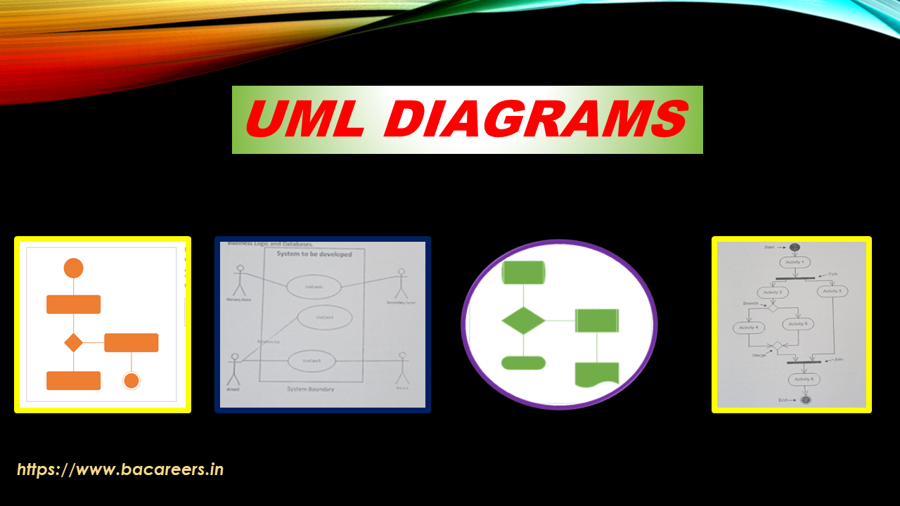
Understanding Sequence Diagram in UML
… Read the rest