1. what is uml diagram ?
UML (Unified Modeling Language) is a standard language that allows software developers to create diagrams that can be shared across different tools. This makes it easy to visualize your design and share it with
In software engineering, UML stands for Unified Modeling Language. It is a standardized visual modeling language used to design, analyze, and communicate system structures and behaviors. UML provides a set of graphical notations that allow software engineers to represent different aspects of a system in a standardized and consistent manner. UML diagrams are the graphical representations of a system’s architecture and design. They help software engineers to visually capture, specify, construct, and document the artifacts of a system. UML diagrams are widely used in the software development process to facilitate communication and collaboration among developers, designers, and stakeholders. There are several types of UML diagrams that serve different purposes in software engineering. Some of the commonly used UML diagrams include:
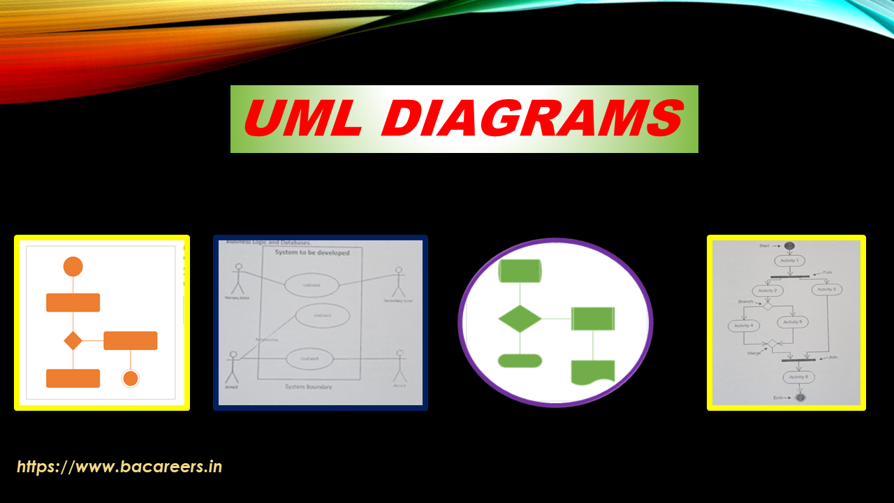
1. Class Diagram: It represents the static structure of a system by showing classes, their attributes, methods, and relationships between classes. Class diagrams are used to visualize the structure of the system and the relationships between its components. 2. Use Case Diagram: It depicts the interactions between the system and its external actors. Use case diagrams show the various functionalities or features that the system provides and how external actors interact with the system. 3. Sequence Diagram: It illustrates the interactions between objects within a system over time. Sequence diagrams show the order of messages exchanged between objects and help in understanding the dynamic behavior of the system. 4. Activity Diagram: It represents the flow of activities within a system. Activity diagrams show the sequential and parallel behavior of processes or workflows in the system. 5. State Machine Diagram: It depicts the states of an object and the transitions between those states. State machine diagrams help in understanding the behavior of an object in response to events or stimuli. 6. Component Diagram: It represents the physical and logical components of a system and their relationships. Component diagrams show how different components of the system are organized and interact with each other. 7. Deployment Diagram: It shows the physical deployment of software components on hardware nodes. Deployment diagrams illustrate how a system is deployed in a distributed environment, including the hardware infrastructure. These are just a few examples of the different types of UML diagrams used in software engineering. Each diagram serves a specific purpose and helps in visualizing and understanding different aspects of a system. UML diagrams provide a standardized way to model and communicate system designs. They help in visualizing complex systems, identifying potential design issues, and documenting system requirements and specifications. UML diagrams can be created using various software tools that support UML modeling, such as Microsoft Visio, Enterprise Architect, and Lucidchart. In conclusion, UML is a standardized visual modeling language used in software engineering to design, analyze, and communicate system structures and behaviors. UML diagrams are graphical representations that help in visualizing and understanding different aspects of a system. They play a vital role in the software development process by facilitating communication, collaboration, and documentation.
UML (Unified Modeling Language) is a standard language that allows software developers to create diagrams that can be shared across different tools. This makes it easy to visualize your design and share it with