

FREE DOWNLOAD: Business Analyst Documentation Toolkit
Get instant access to real-world BRD, FRD, and project story templates used by senior BAs.
Download Free Templates PDFIn Unified Modeling Language (UML) and software engineering, an Activity Diagram is a behavioral diagram that visually maps the step-by-step flow of control, decisions, and parallel activities within a system or business process.
Often described as an advanced or standardized flowchart, an activity diagram helps Business Analysts, System Architects, and Software Engineers model complex business workflows, verify logic execution, and communicate system design to non-technical stakeholders.

Key Components & Symbols of a UML Activity Diagram
Before building activity diagrams, it is essential to understand standard UML notations:
| UML Symbol | Name | Description / Function |
| Solid Black Circle | Initial Node (Start) | Marks the starting point of the activity flow. |
| Rounded Rectangle | Action / Activity Node | Represents a specific task, step, or operation performed. |
| Diamond | Decision Node | Evaluates a condition with guard conditions (e.g., [Valid] or [Invalid]). |
| Horizontal / Vertical Bar | Fork Node | Splits a single incoming flow into multiple parallel concurrent flows. |
| Horizontal / Vertical Bar | Join Node | Combines multiple parallel concurrent flows back into a single flow. |
| Encircled Solid Circle | Final Node (End) | Marks the termination of the entire workflow execution. |
| Columns / Swimlanes | Swimlanes | Group activities by responsible actors (e.g., User, System, Payment Gateway). |
10 Real-World Examples of Activity Diagrams
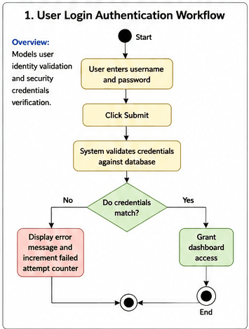
1. User Login Authentication Workflow
Overview: Models user identity validation and security credentials verification.
Flow Steps:
User enters username and password $\rightarrow$ Click Submit.
System validates credentials against database.
Decision Node: If credentials match $\rightarrow$ Grant dashboard access; If invalid $\rightarrow$ Display error message and increment failed attempt counter.
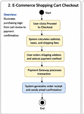
2. E-Commerce Shopping Cart Checkout
Overview: Illustrates purchasing logic from cart review to payment confirmation.
Flow Steps:
User clicks Proceed to Checkout.
System calculates subtotal, taxes, and shipping fees.
User enters shipping address and selects payment method.
Payment Gateway processes transaction.
System generates order receipt and sends email confirmation.
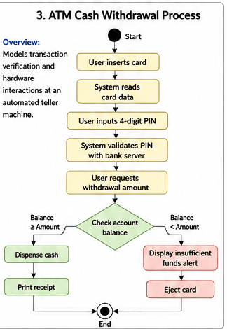
3. ATM Cash Withdrawal Process
Overview: Models transaction verification and hardware interactions at an automated teller machine.
Flow Steps:
User inserts card $\rightarrow$ System reads card data.
User inputs 4-digit PIN $\rightarrow$ System validates PIN with bank server.
User requests withdrawal amount.
Decision Node: Check account balance.
If Balance $\ge$ Amount: Dispense cash $\rightarrow$ Print receipt.
If Balance < Amount: Display insufficient funds alert $\rightarrow$ Eject card.
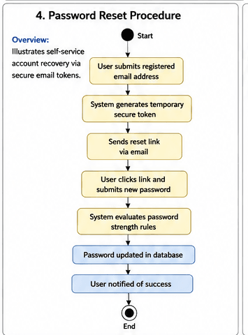
4. Password Reset Procedure
Overview: Illustrates self-service account recovery via secure email tokens.
Flow Steps:
User submits registered email address.
System generates temporary secure token $\rightarrow$ Sends reset link via email.
User clicks link and submits new password.
System evaluates password strength rules.
Password updated in database $\rightarrow$ User notified of success.
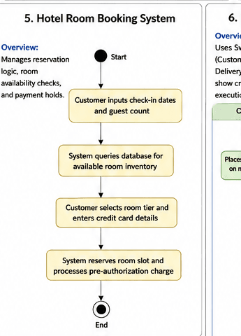
5. Hotel Room Booking System
Overview: Manages reservation logic, room availability checks, and payment holds.
Flow Steps:
Customer inputs check-in dates and guest count.
System queries database for available room inventory.
Customer selects room tier and enters credit card details.
System reserves room slot and processes pre-authorization charge.
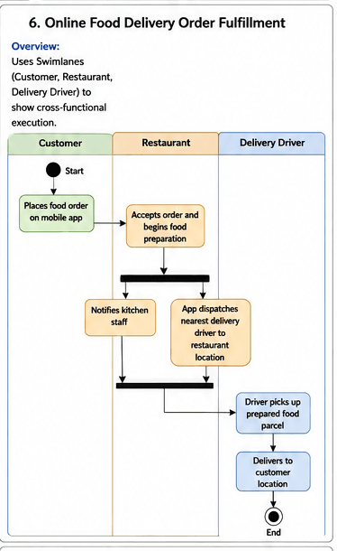
6. Online Food Delivery Order Fulfillment
Overview: Uses Swimlanes (Customer, Restaurant, Delivery Driver) to show cross-functional execution.
Flow Steps:
Customer: Places food order on mobile app.
Restaurant: Accepts order and begins food preparation.
Fork Node (Parallel Execution):
Restaurant notifies kitchen staff.
App dispatches nearest delivery driver to restaurant location.
Join Node: Driver picks up prepared food parcel $\rightarrow$ Delivers to customer location.
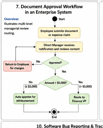
7. Document Approval Workflow in an Enterprise System
Overview: Illustrates multi-level managerial review routing.
Flow Steps:
Employee submits document or expense claim.
Direct Manager receives notification and reviews content.
Decision Node: If approved and amount > $5,000 $\rightarrow$ Route to Finance VP; If approved and amount $\le$ $5,000 $\rightarrow$ Auto-approve for reimbursement.
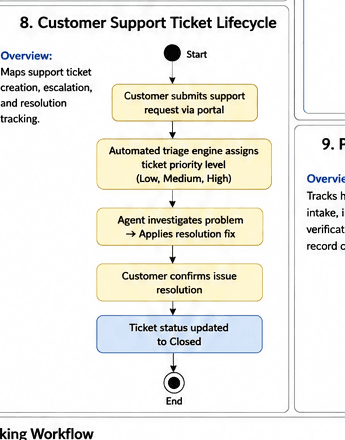
8. Customer Support Ticket Lifecycle
Overview: Maps support ticket creation, escalation, and resolution tracking.
Flow Steps:
Customer submits support request via portal.
Automated triage engine assigns ticket priority level (Low, Medium, High).
Agent investigates problem $\rightarrow$ Applies resolution fix.
Customer confirms issue resolution $\rightarrow$ Ticket status updated to Closed.
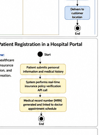
9. Patient Registration in a Hospital Portal
Overview: Tracks healthcare intake, insurance verification, and record creation.
Flow Steps:
Patient submits personal information and medical history.
System performs real-time insurance policy verification API call.
Medical record number (MRN) generated and linked to doctor appointment schedule.
10. Software Bug Reporting & Tracking Workflow
Overview: Maps how QA teams log defects and track engineering resolutions.
Flow Steps:
QA Engineer logs defect details and steps to reproduce.
Lead Developer assigns issue to backend engineer.
Engineer fixes codebase $\rightarrow$ Commits code fix to test environment.
QA re-tests feature $\rightarrow$ If passed, mark as Closed; If failed, Re-open.

Best Practices for Drawing Activity Diagrams
When creating activity diagrams in tools like Lucidchart, Draw.io, Enterprise Architect, or Visio:
Use Swimlanes for Clarity: Group activities by actor or system component to eliminate ambiguity about who performs which action.
Keep Guard Conditions Explicit: Ensure decision paths out of diamonds always feature unambiguous labels like
[Valid]or[Invalid].Balance Granularity: Avoid modeling micro-code execution steps; focus on business-level tasks and functional logic flows.
Ensure Single Initial Node: Maintain a single starting point to keep system execution paths straightforward for developers and stakeholders.
Important Articles
- What is uml Diagram ?
- What is Class Diagram
- BPMN Tools
- What is Use Case?
- What is Use Case Diagram with Example
Frequently Asked Questions (FAQ)
While both depict processes visually, an activity diagram is an official UML standard that explicitly supports parallel/concurrent execution flows (using Fork and Join nodes) and cross-functional role mapping (using Swimlanes), which standard flowcharts lack.
Business Analysts draw activity diagrams during the Requirements Analysis phase to model complex business workflows, refine use cases, and validate logic steps before developers write code specifications.
A guard condition is a boolean statement attached to an output branch of a decision node (e.g., [Age >= 18]). The workflow can only proceed down that path if the guard condition evaluates to true.
🎁 Become a Better Business Analyst
Join 1,200+ Business Analysts learning every week.
Get instant access to:
📘 FREE Business Analyst Templates
🎯 Interview Preparation Guides
🚀 Agile & Scrum Tutorials
🤖 AI for Business Analysts
📈 Career Growth Tips
100% Free • No Spam • Unsubscribe Anytime
